
Building the Radio Telescope Waveguide
Building the Radio Telescope Waveguide
How not to make the same mistakes I made

Looking up at the stars at night makes you wonder - what is out there? Who? And how might we know?
Radio telescopes around the world “listen” to the signals emanating from stars and galaxies beyond the reach of our eyes and even our most powerful optical telescopes. But it’s not just the vast, powerful dishes that are capable of receiving these signals. Low cost, DIY radio telescopes can be built in your backyard, and tuned to receive signals from the Milky Way - what is known as “the hydrogen line”.
In my previous article, I stepped through the building of the foundations of the telescope. It’s a simple construction made of readily available lumber. But the building of the waveguide and horn itself - the subject of this article - is far from simple.
Unfortunately, I built the foundation before turning my attention to the horn and the waveguide. But the smart thing to do would be to start with the most sensitive part of the telescope first - the waveguide.
Build the waveguide first
In my haste to listen to the stars, I jumped into the construction of the horn and the foundations. The horn, wrapped in shiny foil, looks spectacular, and I was miraculously drawn to it. Before I knew it I had constructed an almost square horn, glinting in the sun and promising easy access to intergalactic knowledge. It looked amazing. But it was a mistake that took quite some effort to overcome.
Of course, I could have pulled the horn apart and reworked it, but my stubbornness kicked in and I pressed on.
So why should we start with the waveguide?
Most designs and guides recommend the use of large paint cans or tins that usually contain olive oil. The size of these items are almost perfect for a rectangular telescope horn.
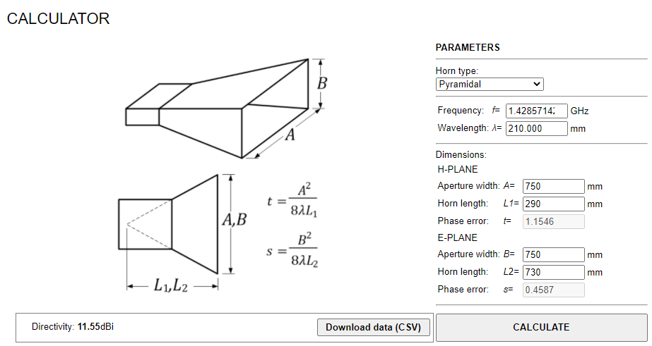
Calculating the dimensions of your waveguide
What I didn’t realise is that the dimensions of the horn and the guide are intimately connected. It is the waveguide size that helps filter out the “noise” of the universe by only capturing the specific frequencies that you are planning to listen for. In our case, we are listening for the Hydrogen Line whose frequency is 1.42Ghz. It’s important to know that the Hydrogen Line’s wavelength is 210mm. And these two parameters together set the dimensions of your waveguide and the horn.
If, like me, can’t find a paint tin or olive oil can, you will need to construct your waveguide to your own dimensions. Using this waveguide calculator will help immensely.
In my case, the horn was close to square - approximately 750mm x 750mm. This meant that I needed an almost square waveguide to match.
I constructed my waveguide out of zinc ceiling flashing. It was relatively simple to cut the sides of the waveguide to shape. Rather than a single piece divided into four and folded, I chose to cut out the four sides and rivet them together. I expected this to provide more strength and rigidity to the waveguide. For the base of the waveguide, I also cut and riveted a piece of flashing to size. Inside the waveguide I covered over the rivets and edges of the flashing with foil tape.
Adding the antenna to the waveguide
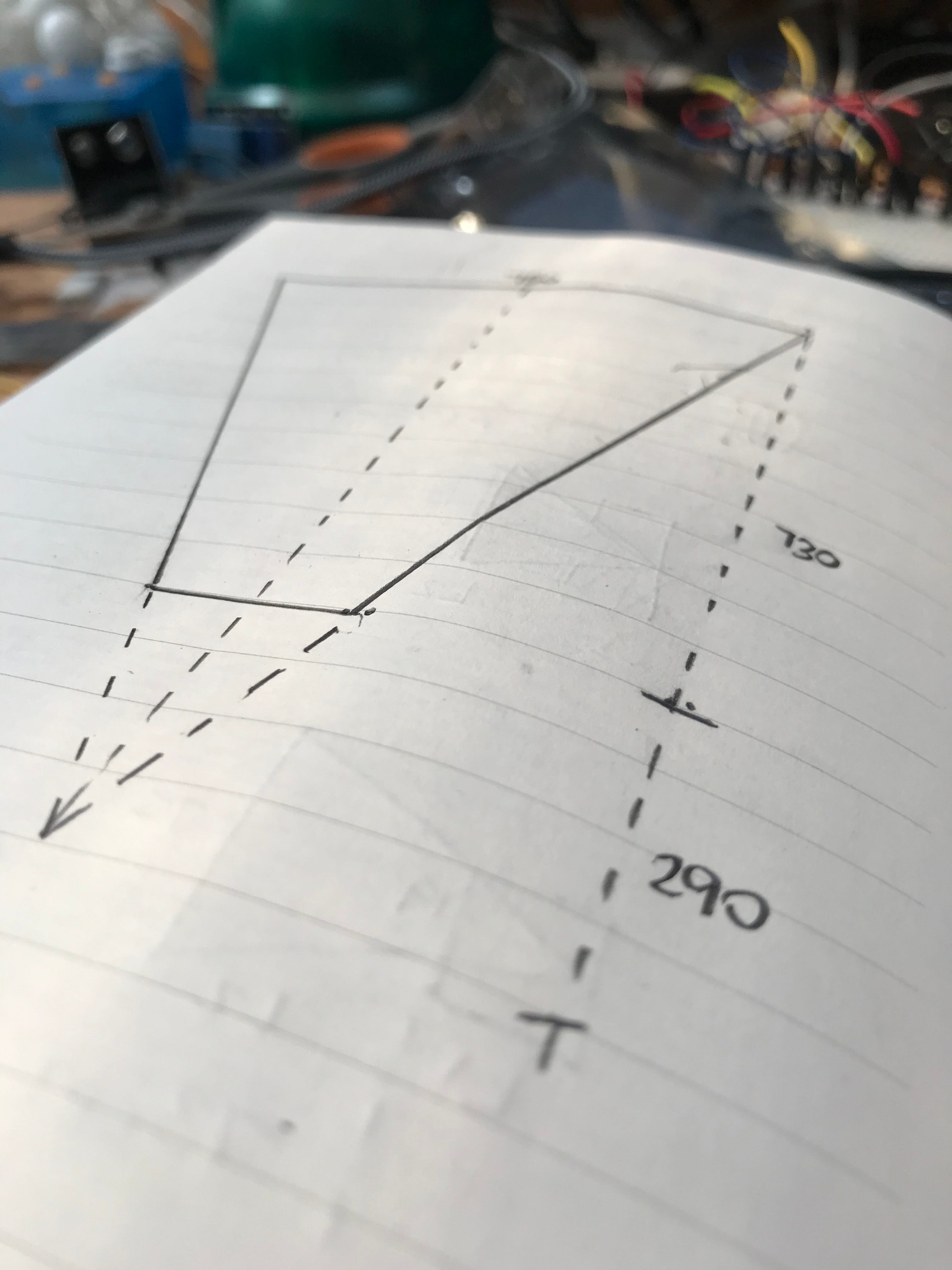
Once you have the waveguide ready, you will need to drill a hole for the antenna. It is important that the antenna is positioned at a specific distance from the bottom of the waveguide - and is centred in the middle of the widest side.

The antenna itself should be one quarter of the wavelength. In this case, we have a wavelength of 210mm which means the antenna should be 52.5mm in length measured from the wall of the waveguide. I used a short length of 6mm copper wire soldered onto an SMA connector and secured by a bolt on the outside of the waveguide.

But where exactly should the antenna be placed? At a simple level, the antenna should be placed one quarter of the wavelength from the base of the waveguide - in this case 52.5mm. Placing a block of wood on the inside of the waveguide makes it easier to drill a hole, and within seconds I was ready to secure the antenna.
Now all I needed was a horn.